Friday, 15 August 2014

Golf Boot Floor v2

Since the last time I cut up the floor the golf hasn't actually run much at all, but thats not down to the floor being missing, far from it. But with that being said the intention is to take this to an event later this year and that means moving a good amount of gear around with it. So it's back to the flooring over the spare wheel for another go.


First off, a template around the rear wheel arches inside to transfer to some 3mm plywood sheet. With the extra weight, this should hold up better than the hardboard did and the whole unit should come out if I really want to go lightweight.


First edge cut...


...and it fits! almost on the first go anyway.


The second edge is cut and with some fine tuning it fits too.


The back of the board has to be cut to fit around a small brace and also just about allows for fingers to lift it with ease.


After a long time thinking about how to do this I had a kind of eureka moment and disappeared into the house and wandered about muttering to myself for about 20 minutes while my dad and girlfriend didnt really know what I was doing.

Using some old Ikea brackets and a dremel I fitted them over some screws meant for the rear seats and wound a wing nut on to hold it in place.


The next part of the epiphany was using some 100mm box trunking as the front support instead of wood. I was going to use wood but it'd be heavier and I didnt have it on hand. This was lying around and had been for a couple years or more.

Some quick cuts with the Dremel to get over the wing nuts and it's ready to fit.


The box section is held on with two screws and a thin strip of wood behind for them to bite into and hopefully not strip. So far so good, the washers work well to spread the load and nothing broke.


The completed, as yet uncovered floor.


And from the other end behind the passenger seat.


Underneath there are a few pieces of pine to add some front to back and a piece wider than the sunken floor so it stays at the right level behind the rear lights.


Next job for this is to cover it and try it out.

Oh right! I forgot...

It suddenly occurred to me, mid way through a project (which i'd neglected to take any pictures of as a result) that I have a blog, fill of things I've done and haven't posted about.

So with a bit of luck i'll remember to post a few this weekend and share some of the projects again. If anyone notices me forget for a prolonged period again, do prod and i'll get back on it.

Fortunately I've started a second today, which I did remember to take pictures of, so that'll be coming soon (maybe) to a browser near, or more likely in front of you.

Wednesday, 11 June 2014

Organise ALL THE THINGS

Now that the extraction is basically sorted in the garage, there's a new problem to be addressed. There never seems to be enough space to DO anything when you want to, because theres so much stuff, and it's typically badly organised from years of being put away in a hurry to do something else 'now'.

After getting a new and somewhat larger band saw, things came to a head when the old one had to move to make room for the new one. The problem being that the old small band saw stood on a table which was later made into a wood store for all different types of wood, and as the collection of bits increased it just got worse.


This is all of the wood which isn't a large sheet piece and was under the benches in various piles. There's Oak, Mahogany, Ash, Walnut, some plywood and chipboard of  various thicknesses and coverings to name only the more common ones.


The old band saw stand was also one of the supports for the main bench top down that side of the garage, not especially helpful when it needs to be removed.


Because the legs themselves were perfectly serviceable, and also held up the shelf that the thicknesser was on, making a new set seemed a bit annoying. Making a filler block and end cap instead to make up the gap was far easier and still did the job. A little hacky, but if it's stupid and it works, it's not stupid.


In a spree of efficiency I also decided to start clearing out ALL of the tools on the other side and reoganising them so they actually worked in a sensible manner. Because of the speed of doing things and trying to finish as much as possible in a short space of time, picture taking fell a little by the wayside while problems were overcome.

On the left of the picture, just visible are some metal shelves, which when they were installed were sufficient as there were fewer tools overall. With the number of tools increasing and 1/3 of this are being taken up by a router table and the shelves being removed, everything was crammed down.

For years the intent has been to make a sliding shelf, and now the time had come, basically because I got sick of moving the rails around the garage and saying "these should be used..."

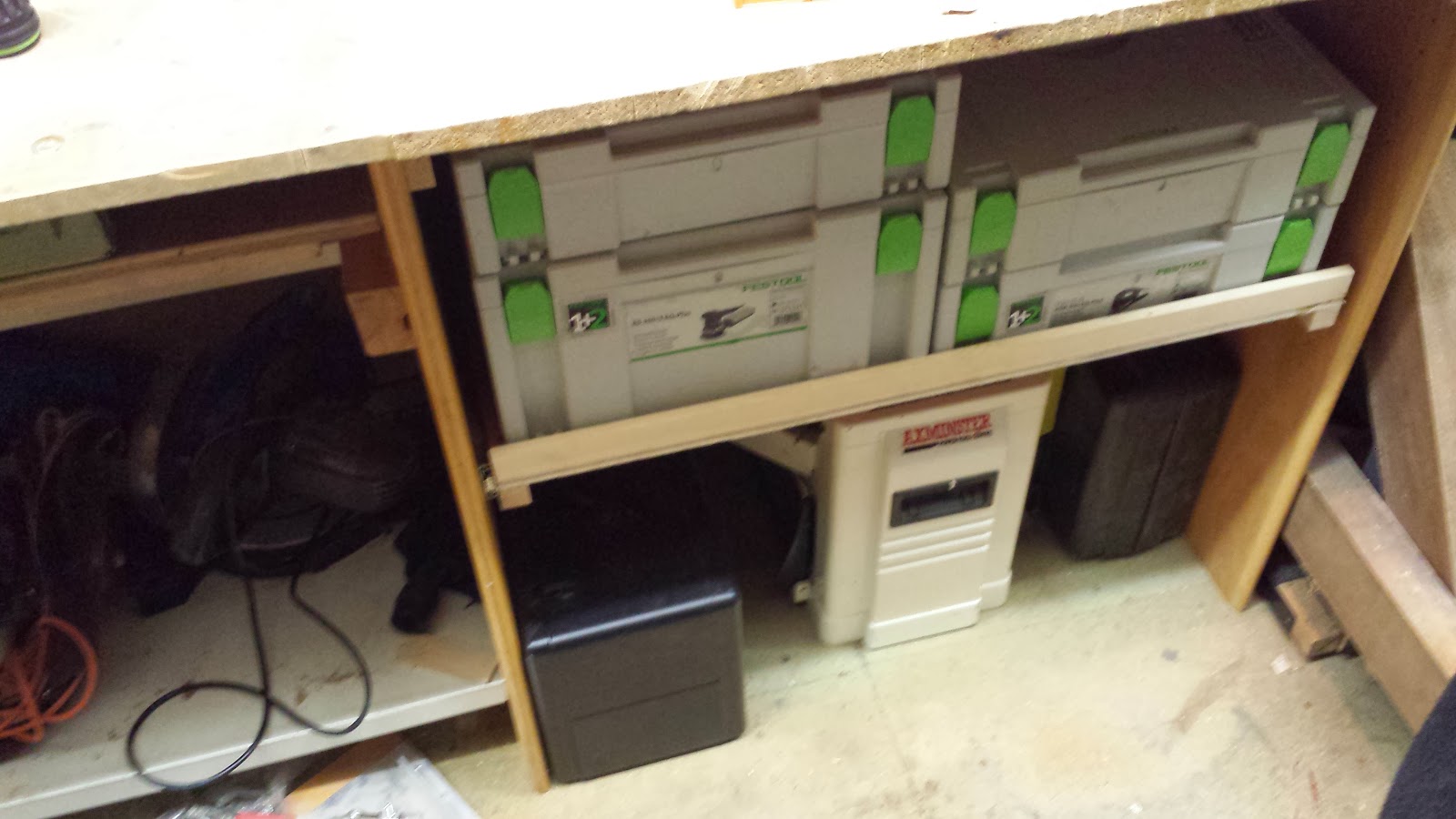
So, a shelf was made to carry all of the Festool boxes since the stack and lift so well, underneath went the router, the thicknesser and the biscuit jointer.


Behind the Festool as the shelf is roughly 24" deep goes the nail gun, the hammer drill and mains screwdriver, circular saw, and an exact-saw, which is pretty handy plus a case of bits.


The space to the left has also been redone, but i'll put up photos of that another time, once i've taken them.

Tuesday, 13 May 2014

Further Extraction

The first part of this project got piping most of the way round the garage and a lot of the more difficult sections in place. Once the pipe was extended along the other side of the garage as well, there was still space for the pile of clamps that usually fall over when trying to take one to be stored properly underneath. 


In addition the down pipes for the tools were added and the blast gates installed.


The gates allow air flow to be controlled so only one part is open, allowing maximum extraction from which ever tool is being used. It's possible to close the whole system off, but it's not really helpful...


There are a few more things to be added like a split pipe to the tablesaw to draw dust from the back of the blade near the riving knife, as well as a better means to collect dust from behind the radial arm saw.


Wednesday, 7 May 2014

LAN In A Box - Part 10, The Cable Finale (Almost)

The last of the cabling took two sessions and actually went pretty quickly. So much so I didn't take that many pictures because it didn't seem interesting enough. 

Here's some patched cables.


Here are all of the patched cables.


There was one minor flaw I noticed really a little late in the day. The new patch panel has it's holes at the outer edge of the U. The old on didn't and had it's mounting holes in the center of the U. As a result, next time the sides pieces are out they'll have to be redrilled for the new panel, but fortunately it's hardly impossibly difficult to do.


This was mean't to be the last update before the first sue of LIAB in the wild, but the PSU died while trying to install the OS so delayed everything, the network side will be ready, but the server itself is probably going to be done at the event.


Friday, 2 May 2014

LAN In A Box - Part 9, Power Up!

 I forgot to take a picture of the brackets for the power supply, but they weren't really all the interesting to see being made. They're more spare aluminium bend round and hammered to fit closer, then screwed and pop riveted into place to allow it to be removed, but still held securely, even to the thin ply on the back.


One thing I had forgotten to do earlier was make the hole for the power cable to actually get to the PSU, as well as the Wireless AP.


Forstner and Festool bit to the rescue! One wasn't enough, so had to double up and make it wider for the kettle plug to get through.


The ideal position for the AP had to be near the top as the box was going to be on the floor, having the AP on the floor wasn't going to help a great deal.

Mounting it at the top in a position where the antenna can fold up also kept it well out of the way of everything inside knocking it when packing. After finding the position where the antenna flipped up and didnt hit the front/lid I made a shelf when a couple of notches to locate the feet of the AP.


The shelf fastened to the side of the box...


And the AP sit's on top. The only down side is that the AP can still fall of the shelf and there's no easy way to fix the AP from underneath without damaging the casing itself.


The solution is a hook shaped bracket, which in retrospect didn't need to be hooked, it could have been a loop as it has to be unscrewed to remove the AP anyway, but never mind.


Here, the antenna is up and the AP fully mounted the the door roughly in place with no collision.


With all the main hardware mounted (at least that I had at the time), one major thing remained, how to power the server on. Quite a few years ago I started making a server case from scratch using aluminium L section and a lot of head scratching. It had a few neat features, one of which was a toaster-mount dvd drive in the top of the case.


 Because the server case took longer to make than it had a use for (I went to rack mounting for my servers) the Buglin switch i bought never actually got used for more than testing. This seems like a good idea to use it, rather than it just sit in a box.

The switch itself has a thread shallower than the thickness of the wood, once again forstner bits to make the hole and recess sorted the problem.


And mounted!


Made a lot of progress in this visit to my parents, back to the homestead to continue with cabling, order parts and setup the server. Unfortunately the spare PSU I had only has a 4 pin 12V connector to the motherboard, but the board itself has an 8 pin. Will be buying an adapter for 4-pin and molex to 8pin connector soon.


Wednesday, 30 April 2014

LAN In A Box - Part 8, Server Mounts

One of the main aims for this was also to have the server in the box for whatever duties were required. A fairly decent core was donated by Sue when she upgraded meaning LIAB will be served by an i5, 8GB of RAM and assuming it works ok, not have to deal with an external GFX card as there is both VGA and DVI on board.

The board is to be mounted up the back of the upper section above the patch panel support by the shelf. Using some 9mm ply works to make a suitable support for the board and shouldn't warp, twisting the board.


The board itself fits nicely as planned with the only problem being mounting it. Standard motherboard stand offs cannot be easily attached to the ply due to the thickness of the wood, and the difficulty of getting nuts for the thread (M3 or 4 x 1.5 it appears)


To solve this, M3 bolts with lock nuts were fixed to the board in the ATX pattern as stand offs to mount the motherboard on to. The regular nuts would then fit over the top of the board and hold it in place while the lock nuts prevented the screws moving.


There is just enough thread taken up by the nuts to leave a gap between the board and the ply across the whole area.


I was going to trim the bolts down, but by the time the board was on it would have been annoying to do, plus threading onto a very short thread is difficult after it's been cut, and they don't get in the way of anything as it stands.


With the board in place the other elements need to be fixed in place too. This will be an SSD for the boot drive and a regular HDD for data storage.


Using some scrap aluminium from an older project I made four brackets to fit the two drives and trimmed them to match one another...


Holes for the screws were added...


Before being placed for the mounting holes to the board. (At this point I could have trimmed the motherboard standoffs down, but I still didn't)


The drives hold in well and don't move around, which is good, at least for the magnetic drive. Originally I was going to mount the SSD direct to the brackets, but then realised i'd drilled the holes for a 3.5" drve and the SSDs were a different pattern. Oops.


Fortunately I had a spare SSD mounting bracket which would work perfectly to fix the problem


Next up, mounting the Server-Board to the back, adding power and WiFi.